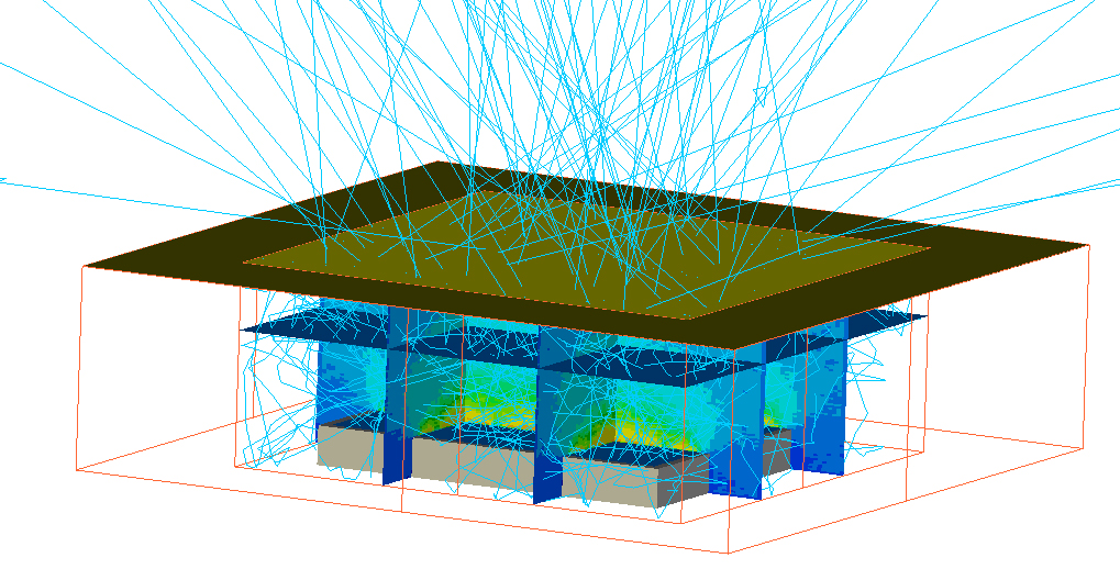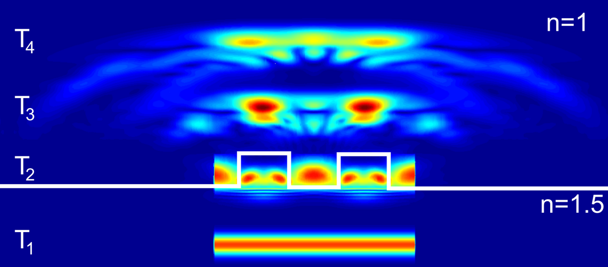
Interaction of a (augmented ) plane-wave (intensity) with a rectangular periodic structure at four different time points (FDTD)
Green Photonics - Virtual Prototyping
The following simulation methods and tools are applied in the context of Virtual Prototyping:
- Ray-tracing (ASAP, Zemax) – Simulation tools based on geometrical optics
- Optimization of the uniformity of color in white light LEDs
- Optimization of the distribution of light intensity and efficiency of LED modules
- Optimization of illumination systems (based on LED, but also on conventional light sources such as halogen and incandescent bulbs and fluorescent tube lighting)
- Reflectors
- Hybrid systems (reflectors + refractive optics)
- Macro- and micro-optics arrays
- Ray-tracing (ASAP, Zemax) – Simulation tools based on geometrical optics Finite Difference Time Domain (FDTD Solutions) - simulation tool based on wave optics
- Calculation and analysis of diffractive structures (structure sizes in the range of the wavelength of light)
- Periodic structures (1D, 2D, 3D mesh)
- Microlens array for light control
- Photonic structures and diffractive optics
- Incoupling and outcoupling structures for solar cells, waveguides, optical sensor devices
- Simulation of particle and surface scattering
- Calculation and analysis of diffractive structures (structure sizes in the range of the wavelength of light)
- Holistic simulation of complex optical systems that have both refractive and diffractive optical components
- Combination of ray tracing and wave optical simulations (FDTD), including interfaces for considerations of data exchange and coherence
- CAD (Rhino, Autocad)
- Modeling and data export of geometries for optics
- Creation of algorithms (MATLAB)
- Calculation of free-form optics
- Data processing and interfaces for data exchange between different simulation methods
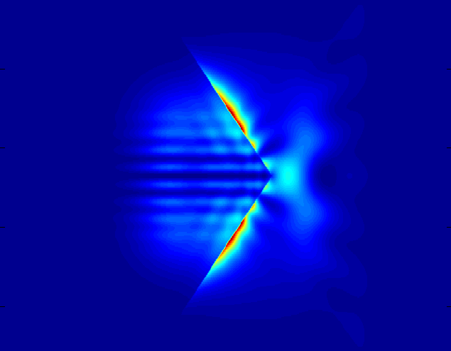
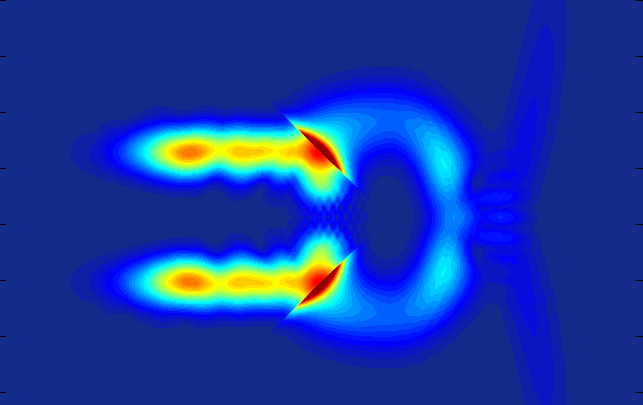
Snapshot of the interaction between a plane-wave (intensity) with a triangular outcoupling structure. Left: wavelength is 10 times smaller than the structure -> total reflection at the edges prevents light outcoupling (evanescent fields visible along the edges); interference at the structure apex causes outcoupling of a small portion of the incident light. Right: the wavelength has the same dimensions as the structure -> outcoupling occurs due to interference effects along the entire structure width